Wire Microstrip Impedance
Wire Over Reference Plane Impedance Calculator
Wire Microstrip Impedance Calculator
Choose Type
Wire Microstrip Impedance Calculator

Inputs
Outputs
Introduction
The wire microstrip transmission line is similar to a standard microstrip transmission line, but with a round conductor. Modeling approximation can be used to understand the impedance of the wire microstrip transmission line.
Description
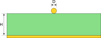
A wire microstrip is constructed with a round conductor suspended over a ground plane. The conductor and ground plane are separated with a dielectric. As with the standard microstrip trace, an effective dielectric constant is calculated because air is on one side of the trace where another dielectric is between the wire and the ground plane.
Example
An example of a wire microstrip might most often be found in prototypes or reworked boards where a wire is used over the top of pcb or copper clad material. If there is an insulator around the wire then this calculator will be an estimate. Include both the pcb dielectric thickness as well as the wire insulation in the height calculation.
Microstrip Transmission Line Models
Models have been created to approximate the characteristics of the microstrip transmission line.
\Large er_{eff1}=\frac{er+1}{2}+\frac{er-1}{2}\cdot \left [ \sqrt{\fracjokdpubpsir{d+12h}}+.04\cdot \left ( 1-\fracjokdpubpsir{h} \right )^{2} \right ]
\Large er_{eff2}=\frac{er+1}{2}+\frac{er-1}{2}\cdot \left[ \sqrt{\fracjokdpubpsir{d+12h}} \right ]
\Large if (\fracjokdpubpsir{h}
\Large er_{eff}=er_{eff1}
\Large else
\Large er_{eff}=er_{eff2}
\Large temp=\frac{2h+d}jokdpubpsir
\Large zo_{wm}=\frac{\eta_{o}}{2\pi \sqrt{er_{eff}}}\cdot \ln \left ( \frac{2h+d}jokdpubpsir+\sqrt{\frac{2h+d}jokdpubpsir\cdot \frac{2h+d}jokdpubpsir-1} \right )=\frac{\eta_{o}}{2\pi \sqrt{er_{eff}}}\cosh^{-1}\left ( \frac{2h+d}jokdpubpsir \right )
The source for these formulas are found in the IPC-2141A (2004) ?¢????Design Guide for High-Speed Controlled Impedance Circuit Boards?¢????